前言
這段時間把AS32 LoRa模組相關的資料大致上看過一遍,需要注意的地方大概如下:
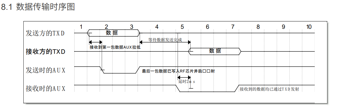
- 這一顆LoRa模組在傳輸的操作上需要配合ACK腳位,特別是在「發送端的第一筆資料」和「在接收前的ACK腳位」。在程式撰寫上可以透過IO腳位的外部中斷來配合操作。
- 在模組內工作模式的切換,要透過IO的腳位設定,才可以切換該模組的工作模式。
| 模式切換 |
MD0腳位 |
MD1腳位 |
| 一般工作模式 |
腳位拉低(Input) |
腳位拉低(Input) |
| 模組設定模式 |
腳位拉高(Output) |
腳位拉高(Output) |

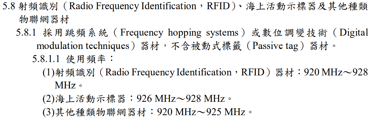
- 同時,之前跟幾個群組中得知無線射頻並不是隨隨便便都能用的,最好在購買及使用前先看一下當地的法規規範,以免觸法。以台灣的無線射頻法規,一般使用者可使用的是920~928 MHz這一範圍的頻段。
其中海上使用的頻段為926~928 MHz,而其他場域可使用920~925 MHz,要購買類似頻段的模組要注意一下當地的法規標示。
- 最後使用這顆LoRa模組需要注意一點:這顆模組並未有拿到NCC(國家通訊傳播委員會)的認證,因此在「台灣境內」僅能用於個人實驗,不可拿去實際場域運作!
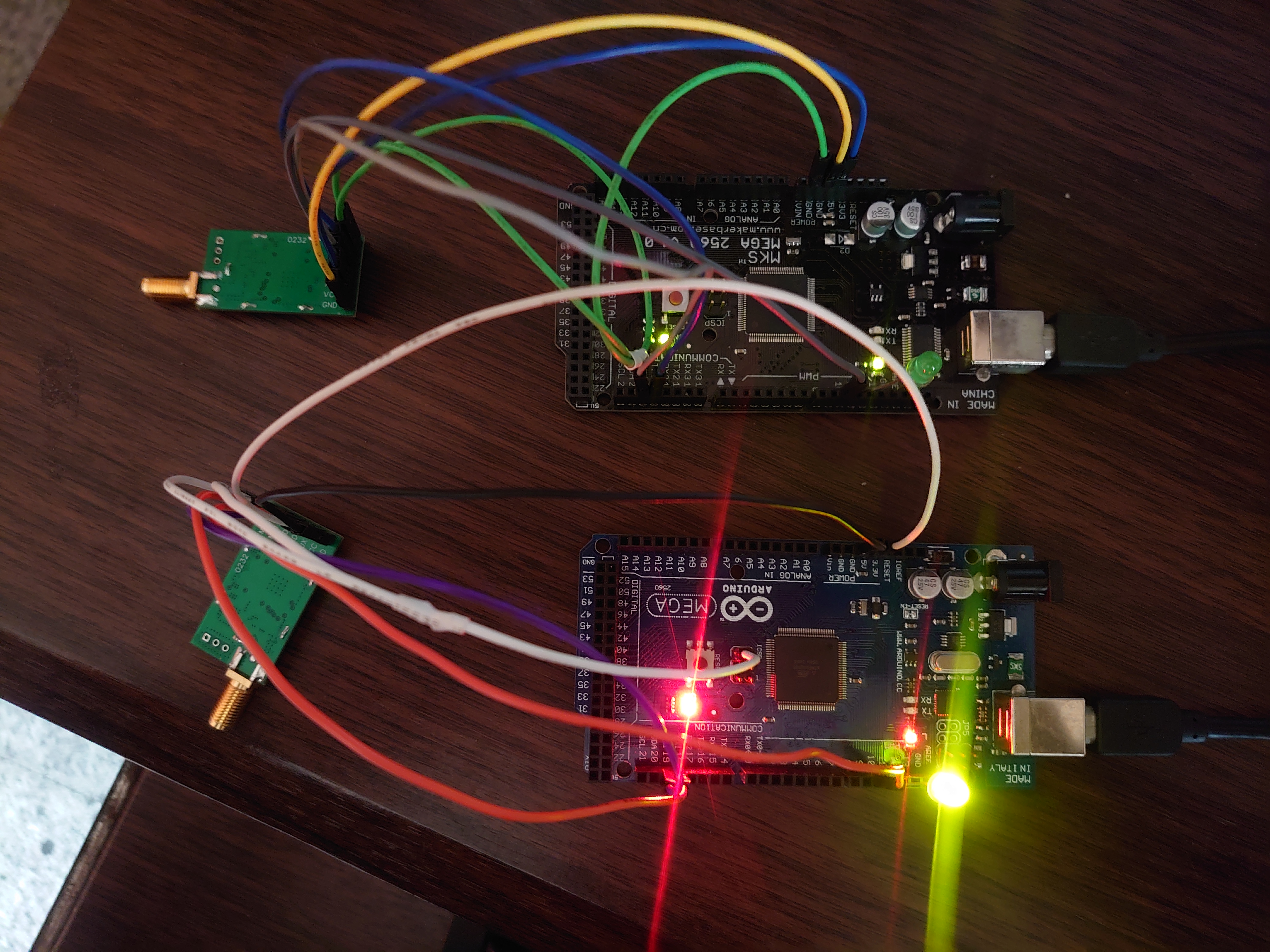
測試方式
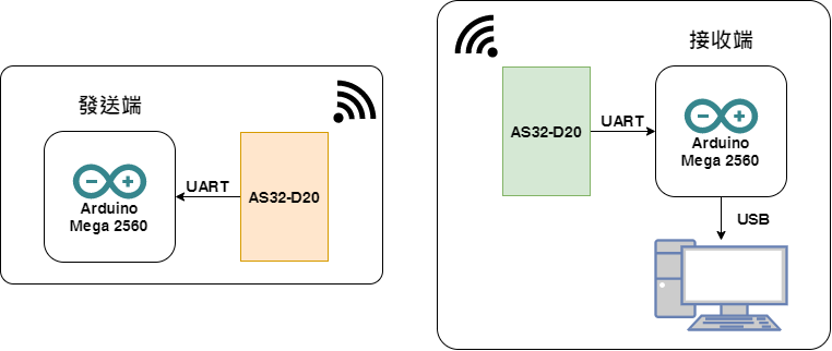
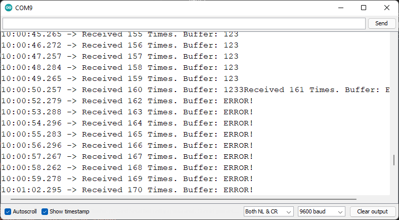
這裡使用兩塊Mega 2560,其中一塊僅連接AS32,並且每秒廣播一筆數據,另一塊連接AS32作為接收端之外,也與PC透過USB連接,並使用Serial Monitor顯示A32收到的數據。
發送端程式碼
1
2
3
4
5
6
7
8
9
10
11
12
13
14
15
16
17
18
19
20
21
22
23
24
25
26
27
28
| #include <avr/io.h>
#define interval_ms 1000
unsigned long currentMillis = 0, preMillis = 0;
void setup()
{
Serial1.begin(9600);
DDRB |= (1 << DDB5);
DDRB &= ~(1 << DDB4);
PORTB &= ~(1 << PB5);
}
void loop()
{
currentMillis = millis();
if(currentMillis - preMillis >= interval_ms)
{
preMillis = currentMillis;
Serial1.println("123");
while((PINB & (1 << PB4)) == 0);
PORTB ^= (1 << PB5);
}
}
|
接收端程式碼
1
2
3
4
5
6
7
8
9
10
11
12
13
14
15
16
17
18
19
20
21
22
23
24
25
26
27
28
29
30
31
32
33
34
35
36
37
38
39
40
41
42
43
44
45
46
47
| #include <avr/io.h>
#include <util/delay.h>
#define interval_ms 6
unsigned long currentMillis = 0, preMillis = 0;
unsigned readCount = 0;
char readBuffer[10] = "", readIndex = 0;
void setup()
{
Serial1.begin(9600);
Serial.begin(9600);
DDRB |= (1 << DDB5);
DDRB &= ~(1 << DDB4);
PORTB &= ~(1 << PB5);
}
void loop()
{
currentMillis = millis();
if(currentMillis - preMillis >= interval_ms)
{
preMillis = currentMillis;
if((PINB & (1 << PB4)) == 0)
{
for(readIndex = 0;readIndex < 5; readIndex++)
readBuffer[readIndex] = Serial1.read();
Serial1.flush();
PORTB ^= (1 << PB5);
Serial.print("Received ");
Serial.print(++readCount);
Serial.print(" Times. Buffer: ");
if(readBuffer[0] == '1' && readBuffer[2] == '3')
Serial.print(readBuffer);
else
Serial.println("ERROR!");
}
}
}
|
過程
上述程式碼中,都有引入millis()以替代delay(),這麼作的方式是利用Arduino Mega 2560內的Timer 計時,可以讓發送端的發送時間更為準確,也不會讓CPU有卡住的情況,導致發送時間不一致。
1
2
3
4
5
6
7
8
9
10
11
12
13
14
15
16
17
18
19
|
#define interval_ms 1000
unsigned long currentMillis = 0, preMillis = 0;
void setup()
{
}
void loop()
{
currentMillis = millis();
if(currentMillis - preMillis >= interval_ms)
{
preMillis = currentMillis;
}
}
|
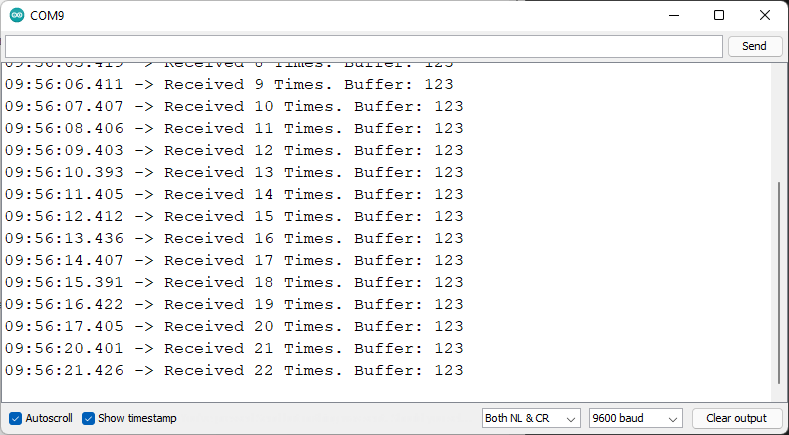
目前的韌體已經可以正常的收發,唯有不定時會出現發送與接收不一致的異常。目前判斷可能是Arduino內的接收方式與我們認知的有些不同,未來若要開發AS32的函式庫可以朝以下兩者前進:
開發照片
參考資料
Comments